The STM32L series has significant low-power performance, and low-power applications are often required in modern electronic products, industrial instruments, wearable devices, and other fields. Therefore, how to design a good low-power application based on STM32L should first accurately understand its seven core working modes.
STM32L4 Low Power Performance
STM32L4 has up to 7 low-power operating modes: supporting seven low-power modes to achieve the best compromise between low power consumption, short startup time, available peripheral devices, and available wake-up sources. Although there are more than 7 modes in the above figure, the values have been refined to describe the 7 working modes according to the STM32L4A6xG datasheet.

This image is from<STM32L4 PWR power control V3.3>, which provides an overview of the performance indicators of the STM32L4 series in terms of low power consumption. Overall, it is still good, with improved flexibility in operating mode options. Reasonably utilizing these working modes can design good low-power products.
Seven working modes
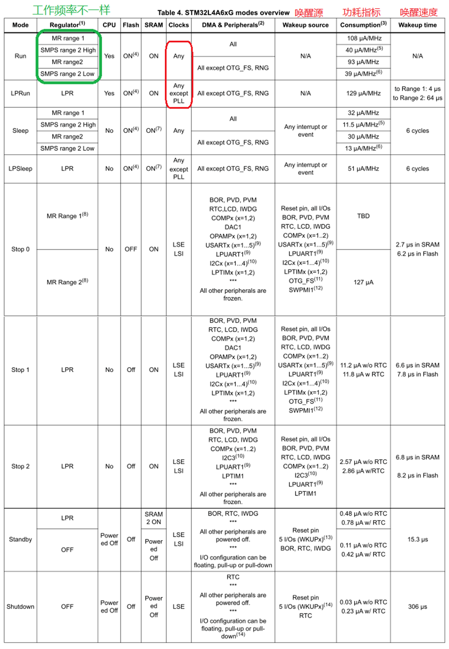
How to read and use this table? Firstly, it is necessary to have a relatively accurate understanding of the physical meaning of the working state represented by each mode of the microcontroller, in order to better design engineering applications based on these working modes.
Run/Sleep mode

Here are several concepts mentioned, MR/SMPS/Range0/Range1:
Here, MR (Main Regulator) refers to the internal Low Dropout Regulator (LDO) low dropout regulator
SMPS (Switching Mode Power Supply) refers to external switch mode power supply. It should be noted that the SMPS solution has higher power efficiency and lower heat loss from a system perspective, but of course, it will increase device costs.
The concept of Range refers to the operating level. For example, in RUN mode, Range 0 allows the CPU to run up to 80MHz, while Range 1 only allows the CPU and peripherals to run up to 26MHz.
Sleep mode: In sleep mode, only the CPU core is sleeping, so the program is paused before going to sleep. What does this mean? The running state of a program is mainly related to the CPU core registers and data in RAM. The so-called CPU sleep refers to the fact that the CPU will no longer perform actions such as finger retrieval, decoding, and execution. After the CPU sleeps, the relevant registers remain unchanged, and the data in RAM remains unchanged. Simply put, it means taking a snapshot of the program's running state and pausing in the snapshot state without changing. When a wake-up event occurs (which is the interrupt/event listed in the table above, collectively referred to as a wake-up event), all peripherals can continue to run and wake up the CPU. The program executes the corresponding interrupt/event handling code and then resumes execution from its pre sleep state.
Let's compare the differences between these two similar patterns:
Similarities: The power supply scheme is the same, and the support for FLASH, SRAM, clock, DMA, and peripherals is basically the same.
Difference: The CPU does not execute instructions in sleep mode.
Low power operation/sleep mode
Low power run (LPRun): In this mode, the CPU can run programs, but it runs slower. How can this low-power operation mode be achieved? Firstly, this mode can be achieved by using a low-power regulator to provide voltage operation for the core logic circuit. Obviously, reducing the operating voltage can significantly reduce power consumption.
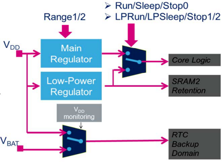
Secondly, reduce the operating frequency of the CPU, which is limited to 2 MHz. The independent clock peripheral can be provided with a clock by HSI16.
Low power sleep (LPSleep): Only low-power operation mode can enter this mode. Only the CPU clock stops, and when awakened, the system will revert back to low-power running mode LPRun.
Stop mode
Stop mode 0/1/2: Stop mode achieves the lowest power consumption while preserving the contents of SRAM and registers. All clocks powered by have stopped running, PLL, MSI RC, HSI16 RC, and HSE crystal oscillators are disabled, but LSE or LSI clocks are in operation.
RTC can maintain its running state (through software configuration, stop mode with RTC and stop mode without RTC can be achieved).
Additionally, certain peripherals with wake-up capabilities can enable the HSI16 RC oscillator in stop mode to detect their wake-up events.
Provide three stop modes: Stop 0, Stop 1, and Stop 2 modes:
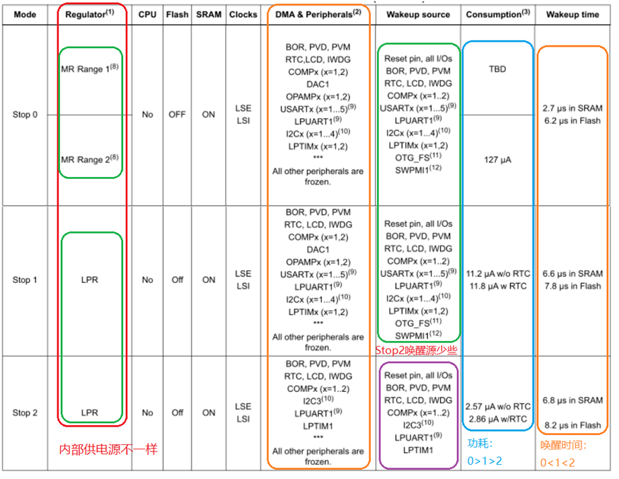
Differences:
The internal power supply for the three modes is different, with Stop0 provided by the MR (Main Regulator) and Stop1/Stop2 provided by the LPR (Low Power Regulator).
The wake-up source Stop2 supports fewer wake-up sources compared to Stop0/Stop1
The required power consumption is Stop0>Stop1>Stop2. Stop0 is powered by MR, so the power consumption is relatively higher among the three modes.
The wake-up time is Stop0<Stop1<Stop2.
Similarities:
The CPU and FLASH are both in a stopped state, while SRAM is still running, which means that the contents of the memory will be preserved. LSE (Low Speed External)/LSI (Low Speed Internal) clock operation provides the running clock for the wake-up source.
Standby/shutdown mode
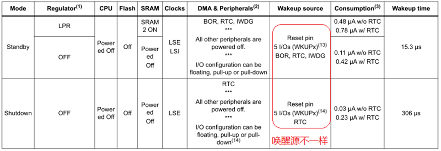
- Standby mode: Standby mode is used to achieve low power consumption through BOR. The internal voltage regulator has been turned off, so all circuits powered by it are turned off, and clock circuits such as PLL, MSI RC, HSI16 RC, and HSE crystal oscillator are also turned off. RTC can be set to run mode (similar to Stop mode, standby mode with RTC and standby mode without RTC can be implemented through software configuration). The status of each I/O in standby mode can be selected through software: internal pull-up/internal pull-down or floating I/O. What is the practical meaning of this sentence? The status setting of the IO port is incorrect, which will have a significant impact on the power consumption of the entire system. It should be set to the minimum current consumption mode. For example, LEDs that are not needed externally should be turned off. After entering standby mode, except for the backup domain and registers in the standby circuit, SRAM1 and register contents will be lost. But SRAM2 can be configured to maintain data retention status. When an external reset (NRST pin), IWDG reset, WKUP wake-up pin event (rising/falling edge) or RTC event (alarm, periodic wake-up, timestamp, tampering) occurs or a fault is detected, the device exits standby mode. The awakened system clock is provided by MSI and can reach up to 8 MHz.
Shutdown mode: The shutdown mode can achieve the lowest power consumption. The internal voltage regulator has been turned off, therefore the power supply has been turned off. PLL, HSI16, MSI, LSI, and HSE oscillators are also turned off. RTC can remain active (it can also be configured through software to be in shutdown mode with RTC or without RTC). BOR is not available in shutdown mode. In this mode, it is not possible to monitor the power supply voltage, therefore switching to the backup domain is not supported. Except for the registers in the backup domain, SRAM1, SRAM2, and register contents will all be lost. When an external reset occurs, that is, when the NRST pin detects a reset event, the WKUP pin event (configurable as a rising or falling edge trigger mode), or the RTC event (alarm, periodic wake-up, timestamp, tampering), the device exits the shutdown mode. The awakened system clock is MSI with a frequency of 4MHz.
Standby mode can achieve device standby function
Shutdown mode can achieve soft boot function
Application development ideas
After analyzing so many work modes, where is their application value? Switching between different modes can seek the best balance between normal device functionality and low power consumption. So what should be done specifically when designing low-power products using STM32L4 series microcontrollers (other microcontrollers have similar strategies)?
Overall, it is actually using the time dimension to switch the working mode of the microcontroller:
Select the working mode, and in some situations where fast processing or high computational time is required, you can choose to let the microcontroller work in RUN mode, as this mode has relatively high power consumption. Therefore, the time slot should be as short as possible to allow the CPU to complete critical processing as soon as possible and switch to sleep or low-power running mode LPRUN.
Reasonably plan the wake-up source. Generally, consideration can be given to the functional requirements of the device: ◆ When the device is in sleep mode, what external interactions need to wake it up. For example, the device has external communication interfaces such as UART/I2C. The device may need to process certain tasks periodically. In this case, a timer can be considered as a wake-up source to wake up the device at a scheduled time and execute a program before entering low-power mode. The specific low-power mode can be flexibly selected based on the parameters in the table above and combined with the device requirements. The device may have external control requirements, such as human-computer interaction interfaces, buttons/touch controls, etc., and also need to be planned as a wake-up source. ◆ ......
Reasonably plan and handle the code for switching between different modes. Generally, wake-up events are implemented from a programming perspective through interrupt handling. Here, internal implementation requires managing the device's operating modes well. It can be implemented using a state machine, and a state diagram can be used to organize it before encoding.
In actual low-power design, in order to minimize the power consumption of the product, such as battery powered products with limited battery energy. So what other perspectives can be planned from a hardware design standpoint? ◆ All peripherals that can be used should be turned off ◆ All clocks that can be used should be turned off ◆ Low frequency operation should be avoided as much as possible. ◆ External high power hardware circuits can be designed with MOSFETs for switch control. In the running state, the corresponding module circuit can be turned on, and in the sleep state, if it does not affect the function, it can be considered to turn off. ◆ External circuits also need to be designed with low power consumption in mind, down to the selection of a resistor. Low power design, the efficiency of the power supply itself is a crucial aspect, do not focus solely on how to program and how to reduce CPU energy consumption. As mentioned earlier, a comprehensive consideration is needed. For example, if a system uses LDO for power supply design, with a large input and output voltage difference, even if other parts are struggling, the system's power consumption is still very high. So where is the energy consumption? In fact, a lot of energy has been consumed by LDO, turning into heat loss and doing useless work. So low-power design, energy is precious, and no link can be missed!
......
Low power design evaluation
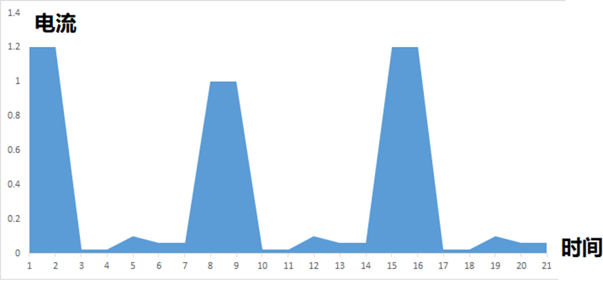
After completing the prototype design of the product, it is essential to evaluate the power consumption of the product. So how to evaluate it? Overall, the current drawn from the product's power supply will exhibit the following form:
A high-speed power supply current acquisition system can be designed to collect the battery power supply current, and then draw the current curve for continuous optimization. Of course, if the company has a good current probe, an oscilloscope can be directly used for evaluation. If the device wakes up periodically, it can basically evaluate the usage time of the system on a fully charged battery under normal conditions. In other external wake-up situations, it is necessary to have a general evaluation based on statistical patterns. The shaded area in the figure can be simply equivalent to the total energy by multiplying it with the supply voltage. Of course, for battery powered systems, the actual discharge curve of the battery also needs to be considered. Generally speaking, as the battery discharges continuously, its voltage will also decrease, which needs to be considered comprehensively in practical applications.
Reference materials:
STM32L4 PWR Power Control V3.3 recommends this official presentation material, which provides a clear description
STM32L4A6xG Datasheet


