The purpose of low-power management in embedded systems is to meet users' performance requirements while minimizing system energy consumption to extend device standby time. The contradiction between high performance and limited battery energy is most prominent in embedded systems, and the joint application of hardware low-power design and software low-power management has become an effective means to solve the contradiction. Various MCUs nowadays provide management interfaces to varying degrees in terms of low power consumption. For example, adjusting the frequency of the main control clock, changing the operating voltage, adjusting or even shutting down the bus frequency, and shutting down the working clock of peripheral devices. With hardware support, reasonable software design becomes the key to energy conservation, and low-power management can generally be divided into three categories:
The main implementation methods of processor power management include dynamic management of CPU frequency and adjustment of working mode during system idle.
The main implementation method of device power management is to turn off individual idle devices
The main implementation method of system platform power management is customized for specific system platforms and unconventional devices.
With the rise of the Internet of Things (IoT), the demand for power consumption in products is becoming increasingly strong. As a sensor node for data collection, it usually needs to work for a long time when powered by batteries, and as a networked SOC, it also needs to have fast response capabilities and low power consumption.
In the initial stage of product development, the first consideration is to complete the functional development of the product as soon as possible. After the product features are gradually improved, it is necessary to add Power Management (PM) function. To meet the demands of IoT, RT Thread provides a power management component. The concept of power management components is to be as transparent as possible, making it easier to add low-power features to the product.
Introduction to PM Components
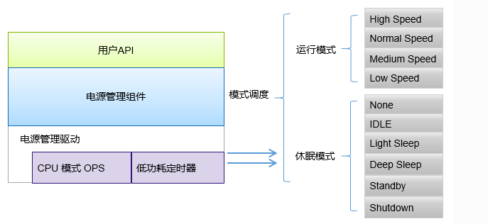
The PM component of RT Thread adopts a layered design concept, separating the architecture and chip related parts, and extracting the common parts as the core. By providing a universal interface for the upper layer, it also makes it easier for the lower layer drivers to adapt to components.
main features
The main features of the RT Thread PM component are as follows:
Manage power consumption based on patterns, dynamically adjust working modes during idle time, and support multiple levels of sleep.
Transparent to applications, components automatically complete power management at the underlying level.
Support dynamic frequency conversion in operation mode, automatically update the frequency configuration of the device according to the mode, ensuring normal operation in different operation modes.
Support device power management, automatically manage device suspension and recovery based on mode, ensuring correct suspension and recovery in different sleep modes.
Support optional sleep time compensation, allowing applications that rely on OS Tick to use transparently.
Provide device interfaces to the upper layer, and if the devfs component is opened, it can also be accessed through the file system interface.
working principle
The essence of low power consumption is that the CPU stops working when the system is idle, and continues to work after interrupts or events wake up. In RTOS, there is usually an IDLE task that has the lowest priority and remains ready. When a high priority task is not ready, the OS executes the IDLE task. Generally, when low-power processing is not performed, the CPU loops through empty instructions in IDLE tasks. The power management component of RT Thread effectively reduces system power consumption by managing CPU, clock, and devices in IDLE tasks.
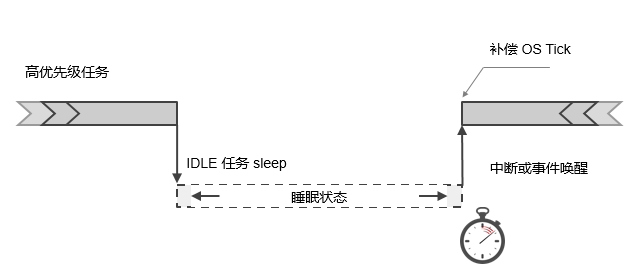
As shown in the above figure, when a high priority task finishes running or is suspended, the system will enter the IDLE task. After the IDLE task is executed, it will determine whether the system can enter sleep mode (to save power consumption). If it is possible to enter sleep mode, some hardware modules will be shut down according to the chip situation, and OS Tick is also likely to enter a pause state. At this point, the power management framework will calculate the next timeout point based on the system timer situation, and set a low-power timer so that the device can wake up at this time and proceed with subsequent work. When the system is awakened by a low-power timer interrupt or other wake-up interrupt source, the system also needs to know the length of sleep time and compensate for the OS tick value to adjust it to the correct value.
Low power consumption state and mode
The RT Thread PM component divides the system into two states: Run and Sleep. Control the frequency of the CPU based on its operating status, suitable for frequency conversion scenarios; The sleep state implements the sleep CPU based on SOC characteristics to reduce power consumption. The two states use different API interfaces and are independently controlled.
The sleep state, also known as the low-power state in general, reduces system power consumption by shutting down peripherals and executing SOC power management interfaces. The sleep state is divided into six modes, presented in the form of a pyramid. The characteristic of gradually decreasing power consumption as the mode increases. The following is the definition of sleep mode. Developers can implement corresponding modes based on specific SOC, but they need to follow the characteristic of gradually reducing power consumption.

- 运行状态运行状态通常用于改变 CPU 的运行频率,独立于休眠模式。当前运行状态划分了四个等级:高速、正常、中速、低速,如下:

Implementation interface of PM component
In the RT Therad PM component, peripherals or applications vote for the desired power consumption mode through a voting mechanism. When the system is idle, the appropriate power consumption mode is determined based on the number of votes, and an abstract interface is called to control the chip to enter a low-power state, thereby reducing system power consumption. When no voting is conducted, it will enter the default mode (usually idle mode).
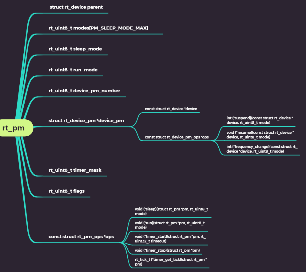
Control block of PM component:
API接口:
void rt_pm_request(uint8_t sleep_mode);sleep_mode 取以下枚举值:
enum
{
    /* sleep modes */
    PM_SLEEP_MODE_NONE = 0,    /* 活跃状态 */
    PM_SLEEP_MODE_IDLE,        /* 空闲模式(默认) */
    PM_SLEEP_MODE_LIGHT,       /* 轻度睡眠模式 */
    PM_SLEEP_MODE_DEEP,        /* 深度睡眠模式 */
    PM_SLEEP_MODE_STANDBY,     /* 待机模式 */
    PM_SLEEP_MODE_SHUTDOWN,    /* 关断模式 */
    PM_SLEEP_MODE_MAX,
};
调用该函数会将对应的模式计数加1,并锁住该模式。此时如果请求更低级别的功耗模式,将无法进入,只有释放(解锁)先前请求的模式后,系统才能进入更低的模式;向更高的功耗模式请求则不受此影响。该函数需要和 rt_pm_release 配合使用,用于对某一阶段或过程进行保护。下面是具体代码实现:
void rt_pm_request(rt_uint8_t mode)
{
    rt_base_t level;
    struct rt_pm *pm;

    if (_pm_init_flag == 0)
        return;

    if (mode > (PM_SLEEP_MODE_MAX - 1))
        return;

    level = rt_hw_interrupt_disable();
    pm = &_pm;
    if (pm->modes[mode] < 255)
        pm->modes[mode] ++;//将对应的模式计数加1
    rt_hw_interrupt_enable(level);
}
void rt_pm_release(uint8_t sleep_mode);调用该函数会将对应的模式计数减1,配合 rt_pm_request 使用,释放先前请求的模式。下面是具体代码实现:
void rt_pm_release(rt_uint8_t mode)
{
    rt_ubase_t level;
    struct rt_pm *pm;

    if (_pm_init_flag == 0)
        return;

    if (mode > (PM_SLEEP_MODE_MAX - 1))
        return;

    level = rt_hw_interrupt_disable();
    pm = &_pm;
    if (pm->modes[mode] > 0)
        pm->modes[mode] --;//将对应的模式计数减1
    rt_hw_interrupt_enable(level);
}
特殊情况下,比如某个阶段并不允许系统进入更低的功耗模式,此时可以通过 rt_pm_request 和 rt_pm_release 对该过程进行保护。如 I2C 读取数据期间,不允许进入深度睡眠模式(可能会导致外设停止工作),因此可以做如下处理:
/* 请求轻度睡眠模式(I2C外设该模式下正常工作) */
rt_pm_request(PM_SLEEP_MODE_LIGHT);

/* 读取数据过程 */

/* 释放该模式 */
rt_pm_release(PM_SLEEP_MODE_LIGHT);
int rt_pm_run_enter(uint8_t run_mode);run_mode 可以取以下枚举值:
enum
{
    /* run modes*/
    PM_RUN_MODE_HIGH_SPEED = 0,    /* 高速 */
    PM_RUN_MODE_NORMAL_SPEED,      /* 正常(默认) */
    PM_RUN_MODE_MEDIUM_SPEED,      /* 中速 */
    PM_RUN_MODE_LOW_SPEED,         /* 低速 */
    PM_RUN_MODE_MAX,
};
调用该函数改变 CPU 的运行频率,从而降低运行时的功耗。此函数只提供级别,具体的 CPU 频率应在移植阶段视实际情况而定。
下面是具体代码实现:
int rt_pm_run_enter(rt_uint8_t mode)
{
    rt_base_t level;
    struct rt_pm *pm;

    if (_pm_init_flag == 0)
        return -RT_EIO;

    if (mode > PM_RUN_MODE_MAX)
        return -RT_EINVAL;

    level = rt_hw_interrupt_disable();
    pm = &_pm;
    if (mode < pm->run_mode)
    {
        /* change system runing mode */
        pm->ops->run(pm, mode);
        /* changer device frequency */
        _pm_device_frequency_change(mode);
    }
    else
    {
        pm->flags |= RT_PM_FREQUENCY_PENDING;
    }
    pm->run_mode = mode;
    rt_hw_interrupt_enable(level);

    return RT_EOK;
}
void rt_pm_notify_set(void (*notify)(uint8_t event, uint8_t mode, void *data), void *data);event 为以下两个枚举值,分别标识进入/退出休眠模式。
enum
{
    RT_PM_ENTER_SLEEP = 0,    /* 进入休眠模式 */
    RT_PM_EXIT_SLEEP,         /* 退出休眠模式 */
};
在应用进入/退出休眠模式会触发回调通知。下面是具体代码实现:
void rt_pm_notify_set(void (*notify)(rt_uint8_t event, rt_uint8_t mode, void *data), void *data)
{
    _pm_notify.notify = notify;
    _pm_notify.data = data;
}
void rt_pm_device_register(struct rt_device *device, const struct rt_device_pm_ops *ops)与应用不同,某些外设可能在进入低功耗状态时执行特定操作,退出低功耗时采取措施恢复,此时可以通过注册PM设备来实现。通过注册 PM 设备,在进入低功耗状态之前,会触发注册设备的 suspend 回调,开发者可在回调里执行自己的操作;类似地,从低功耗状态退出时,也会触发 resume 回调。运行模式下的频率改变同样会触发设备的 frequency_change 回调。下面是具体代码实现:
void rt_pm_device_register(struct rt_device *device, const struct rt_device_pm_ops *ops)
{
    rt_base_t level;
    struct rt_device_pm *device_pm;

    RT_DEBUG_NOT_IN_INTERRUPT;

    level = rt_hw_interrupt_disable();

    device_pm = (struct rt_device_pm *)RT_KERNEL_REALLOC(_pm.device_pm,
                (_pm.device_pm_number + 1) * sizeof(struct rt_device_pm));
    if (device_pm != RT_NULL)
    {
        _pm.device_pm = device_pm;
        _pm.device_pm[_pm.device_pm_number].device = device;
        _pm.device_pm[_pm.device_pm_number].ops    = ops;
        _pm.device_pm_number += 1;
    }

    rt_hw_interrupt_enable(level);
}
The callback notification process for entering/exiting sleep mode and registering as a device:
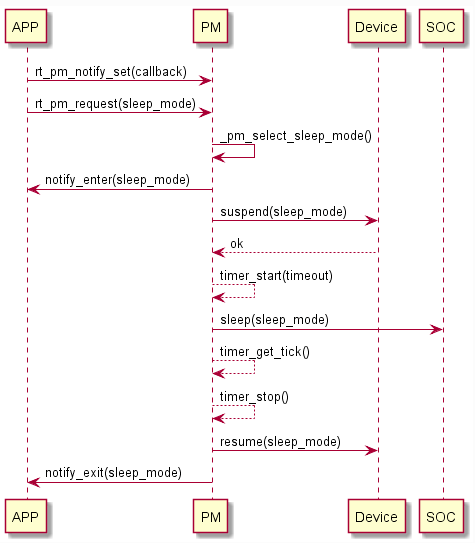
First, set the callback function for entering and exiting the sleep state, and then call rt_pm_request to request the sleep mode to trigger the sleep operation; The PM component checks the sleep mode count when the system is idle and provides recommended modes based on the number of votes; Then the PM component calls notfiy to notify the application that it is about to enter sleep mode; Then perform a suspend operation on the registered PM device, return OK, and execute the sleep mode implemented by SOC. The system enters the sleep state (if time compensation is enabled, a low-power timer will be started before sleep). At this point, the CPU stops working and waits for an event or interrupt to wake it up. After the system is awakened, due to the global interrupt being in a closed state, the system continues to execute from there, obtaining sleep time compensation for the system's heartbeat, sequentially waking up the devices, and notifying the application to exit from sleep mode. After completing such a cycle, exit and wait for the system to idle next time.
Implementation of mode switching code: When the task enters an idle thread, this function is ultimately called to enter low-power and wake-up mode
static void _pm_change_sleep_mode(struct rt_pm *pm, rt_uint8_t mode)
{
    rt_tick_t timeout_tick, delta_tick;
    rt_base_t level;
    int ret = RT_EOK;

    if (mode == PM_SLEEP_MODE_NONE)
    {
        pm->sleep_mode = mode;
        pm->ops->sleep(pm, PM_SLEEP_MODE_NONE);
    }
    else
    {
        level = rt_pm_enter_critical(mode);

        /* Notify app will enter sleep mode */
        if (_pm_notify.notify)
            _pm_notify.notify(RT_PM_ENTER_SLEEP, mode, _pm_notify.data);

        /* Suspend all peripheral device */
        ret = _pm_device_suspend(mode);
        if (ret != RT_EOK)
        {
            _pm_device_resume(mode);
            if (_pm_notify.notify)
                _pm_notify.notify(RT_PM_EXIT_SLEEP, mode, _pm_notify.data);
            rt_pm_exit_critical(level, mode);

            return;
        }

        /* Tickless*/
        if (pm->timer_mask & (0x01 << mode))
        {
            timeout_tick = rt_timer_next_timeout_tick();
            if (timeout_tick == RT_TICK_MAX)
            {
                if (pm->ops->timer_start)
                {
                    pm->ops->timer_start(pm, RT_TICK_MAX);
                }
            }
            else
            {
                timeout_tick = timeout_tick - rt_tick_get();
                if (timeout_tick < RT_PM_TICKLESS_THRESH)
                {
                    mode = PM_SLEEP_MODE_IDLE;
                }
                else
                {
                    pm->ops->timer_start(pm, timeout_tick);
                }
            }
        }

        /* enter lower power state */
        pm->ops->sleep(pm, mode);

        /* wake up from lower power state*/
        if (pm->timer_mask & (0x01 << mode))
        {
            delta_tick = pm->ops->timer_get_tick(pm);
            pm->ops->timer_stop(pm);
            if (delta_tick)
            {
                rt_tick_set(rt_tick_get() + delta_tick);
                rt_timer_check();
            }
        }

        /* resume all device */
        _pm_device_resume(pm->sleep_mode);

        if (_pm_notify.notify)
            _pm_notify.notify(RT_PM_EXIT_SLEEP, mode, _pm_notify.data);

        rt_pm_exit_critical(level, mode);
    }
}
Implementation principle of transplantation
The RT Thread low-power management system is designed to separate the operating mode and sleep mode for independent management. The operating mode is used for frequency and voltage conversion, while the sleep mode calls on the sleep characteristics of the chip. For most chips and developers, it may not be necessary to consider frequency and voltage conversion, only focus on sleep mode. The implementation of underlying functions has already been fully adapted by Sunwancn for STM32. The following are the underlying implementation principles, and users can also customize or enhance the underlying layers according to their own situation. (Note: There may be updates to the driver. Please download the latest PM driver from Gitee for porting. The address is in the pm-ports-stm32 new branch:) https://gitee.com/sunwancn/rt-thread/tree/pm-ports-stm32-new )
The underlying functionality of PM components is accomplished through functions within the struct rt_pm_ops structure:
/**
 * low power mode operations
 */
struct rt_pm_ops
{
    void (*sleep)(struct rt_pm *pm, uint8_t mode);
    void (*run)(struct rt_pm *pm, uint8_t mode);
    void (*timer_start)(struct rt_pm *pm, rt_uint32_t timeout);
    void (*timer_stop)(struct rt_pm *pm);
    rt_tick_t (*timer_get_tick)(struct rt_pm *pm);
};- 移植休眠模式移植休眠模式仅需关注 sleep 接口,下面是具体的实现:
void stm32_sleep(struct rt_pm *pm, rt_uint8_t mode)
{
    switch (mode)
    {
    case PM_SLEEP_MODE_NONE:
        break;

    case PM_SLEEP_MODE_IDLE:
        if (pm->run_mode == PM_RUN_MODE_LOW_SPEED)
        {
            /* Enter LP SLEEP Mode, Enable low-power regulator */
            HAL_PWR_EnterSLEEPMode(PWR_LOWPOWERREGULATOR_ON, PWR_SLEEPENTRY_WFI);
        }
        else
        {
            /* Enter SLEEP Mode, Main regulator is ON */
            HAL_PWR_EnterSLEEPMode(PWR_MAINREGULATOR_ON, PWR_SLEEPENTRY_WFI);
        }
        break;

    case PM_SLEEP_MODE_LIGHT:
        if (pm->run_mode == PM_RUN_MODE_LOW_SPEED)
        {
            __HAL_FLASH_SLEEP_POWERDOWN_ENABLE();
            /* Enter LP SLEEP Mode, Enable low-power regulator */
            HAL_PWR_EnterSLEEPMode(PWR_LOWPOWERREGULATOR_ON, PWR_SLEEPENTRY_WFI);
            __HAL_FLASH_SLEEP_POWERDOWN_DISABLE();
        }
        else
        {
            /* Enter SLEEP Mode, Main regulator is ON */
            HAL_PWR_EnterSLEEPMode(PWR_MAINREGULATOR_ON, PWR_SLEEPENTRY_WFI);
        }
        break;

    case PM_SLEEP_MODE_DEEP:
        /* Disable SysTick interrupt */
        CLEAR_BIT(SysTick->CTRL, (rt_uint32_t)SysTick_CTRL_TICKINT_Msk);

        if (pm->run_mode == PM_RUN_MODE_LOW_SPEED)
        {
            /* Clear LPR bit to back the normal run mode */
            CLEAR_BIT(PWR->CR1, PWR_CR1_LPR);
            /* Enter STOP 2 mode  */
            HAL_PWREx_EnterSTOP2Mode(PWR_STOPENTRY_WFI);
            /* Set Regulator parameter to lowpower run mode */
            SET_BIT(PWR->CR1, PWR_CR1_LPR);
        }
        else
        {
            /* Enter STOP 2 mode  */
            HAL_PWREx_EnterSTOP2Mode(PWR_STOPENTRY_WFI);
        }

        /* Enable SysTick interrupt */
        SET_BIT(SysTick->CTRL, (rt_uint32_t)SysTick_CTRL_TICKINT_Msk);
        /* Re-configure the system clock */
        systemclock_reconfig(pm->run_mode);
        break;

    case PM_SLEEP_MODE_STANDBY:
        __HAL_PWR_CLEAR_FLAG(PWR_FLAG_WU);
        /* Enter STANDBY mode */
        HAL_PWR_EnterSTANDBYMode();
        break;

    case PM_SLEEP_MODE_SHUTDOWN:
        __HAL_PWR_CLEAR_FLAG(PWR_FLAG_WU);
        /* Enter SHUTDOWNN mode */
        HAL_PWREx_EnterSHUTDOWNMode();
        break;

    default:
        RT_ASSERT(0);
        break;
    }
}- In some cases, when porting time compensation interfaces, we may need the system to enter Stop mode during idle time to achieve lower power consumption. According to the manual, Stop 2 mode will turn off the system clock, and the current OS Tick is based on the kernel's Systick timer. So after the system clock stops, OS Tick will also stop. For some applications that rely on OS Tick, when entering Stop 2 mode and being interrupted to wake up, problems may occur. Therefore, it is necessary to compensate for OS Tick after the system wakes up. In Stop 2 mode, the vast majority of peripherals stop working, except for low-power timer 1 (LP_TIM1) and RTC. After selecting LSI as the clock source, they can still run normally, so LP_TIM1 or RTC can be chosen as the time compensation timer for Stop 2 mode.
The time compensation for sleep requires the implementation of three interfaces, which are used to start the low-power timer, stop the timer, and obtain the sleep Tick after waking up. The following is the specific implementation:
static void stm32_pm_timer_start(struct rt_pm *pm, rt_uint32_t timeout)
{
    RT_ASSERT(pm != RT_NULL);
    RT_ASSERT(timeout > 0);

    if (timeout != RT_TICK_MAX)
    {
        /* Convert OS Tick to PM timer timeout value */
        timeout = stm32_pm_tick_from_os_tick(timeout);
        if (timeout > stm32_pmtim_get_tick_max())
        {
            timeout = stm32_pmtim_get_tick_max();
        }

        /* Enter PM_TIMER_MODE */
        stm32_pmtim_start(timeout);
    }
}
static void stm32_pm_timer_stop(struct rt_pm *pm)
{
RT_ASSERT(pm != RT_NULL);
/* Reset PM timer status */
stm32_pmtim_stop();
}static rt_tick_t stm32_pm_timer_get_tick(struct rt_pm *pm)
{
rt_uint32_t timer_tick;
RT_ASSERT(pm != RT_NULL);
timer_tick = stm32_pmtim_get_current_tick();
return stm32_os_tick_from_pm_tick(timer_tick);
}The transplantation of sleep time compensation is relatively simple. According to the Tick configuration, the low-power timer will time out. After waking up, the actual sleep time will be obtained and converted to OS Tick, and the PM component will be informed.
To transplant the running mode and sleep mode, only focus on the run interface. Here is the specific implementation:
void stm32_run(struct rt_pm *pm, rt_uint8_t mode)
{
    static rt_uint32_t last_mode;
    static char *run_str[] = PM_RUN_MODE_NAMES;
    struct rcc_conf_struct sconf = _rcc_conf[mode];

    if (mode == last_mode)
        return;

    if (stm32_run_freq[mode][0] != stm32_run_freq[last_mode][0])
    {
        if (_rcc_conf[last_mode].low_pow_run_en && !sconf.low_pow_run_en)
        {
            /* Disable the Low-power Run mode */
            HAL_PWREx_DisableLowPowerRunMode();
        }

        systemclock_msi_on(last_mode);

        if (mode < last_mode)
        {
            /* Frequency increase */
            HAL_PWREx_ControlVoltageScaling(sconf.volt_scale);

            _set_sysclock[mode]();
        }
        else
        {
            /* Frequency reduce */
            _set_sysclock[mode]();

            HAL_PWREx_ControlVoltageScaling(sconf.volt_scale);
        }

        if (sconf.volt_scale == PWR_REGULATOR_VOLTAGE_SCALE2 || _osc_conf.osc_type == RCC_OSCILLATORTYPE_MSI)
        {
            /* Configure the wake up from stop clock to MSI */
            __HAL_RCC_WAKEUPSTOP_CLK_CONFIG(RCC_STOP_WAKEUPCLOCK_MSI);
        }
        else
        {
            /* Configure the wake up from stop clock to HSI */
            __HAL_RCC_WAKEUPSTOP_CLK_CONFIG(RCC_STOP_WAKEUPCLOCK_HSI);
        }

        if (sconf.low_pow_run_en)
        {
            /* Enable the Low-power Run mode */
            HAL_PWREx_EnableLowPowerRunMode();
        }

        systemclock_msi_off(mode);

#if defined(RT_USING_SERIAL)
        /* Re-Configure the UARTs */
        uart_console_reconfig();
#endif
        /* Re-Configure the Systick time */
        HAL_SYSTICK_Config(HAL_RCC_GetHCLKFreq() / RT_TICK_PER_SECOND);
        /* Re-Configure the Systick */
        HAL_SYSTICK_CLKSourceConfig(SYSTICK_CLKSOURCE_HCLK);
    }

    last_mode = mode;
    rt_kprintf("switch to %s mode, frequency = %d %sHz\n",
               run_str[mode], stm32_run_freq[mode][0], (stm32_run_freq[mode][1] == 1) ? "M" : "K");

    if ((stm32_run_freq[mode][0] / stm32_run_freq[mode][1]) > OSC_CONF_SYS_FREQ_MAX)
        rt_kprintf("warning: The frequency has over than %d MHz\n", OSC_CONF_SYS_FREQ_MAX);
}- 自定义运行级别时钟树配置函数PM 组件驱动在给定运行频率时,已经尽量自动最优化配置时钟树,但有时外设时钟还是没有达到自己想要的频率,这时可以自己配置时钟树,在 board.c 添加以下单个或所有函数,代码可参考
SystemClock_Config()函数:
rt_uint16_t stm32_run_freq[PM_RUN_MODE_MAX][2] =
{
    /* The actual frequency is 1/divisor MHz, divisor = {1, 1000} */
    /* {sysclk frequency, divisor} */
    {/* 配置高频运行时的时钟 */, /* 分频系数 */},    /* High speed */
    {/* 配置普通运行时的时钟 */, /* 分频系数 */},    /* Normal speed */
    {/* 配置中低运行时的时钟 */, /* 分频系数 */},    /* Medium speed */
    {/* 配置低频运行时的时钟 */, /* 分频系数 */},    /* Low speed, MSI clock 2.0 MHz */
};
void stm32_systemclock_high(void)
{
    /* 添加代码,配置高频运行时的时钟树 */
}
void stm32_systemclock_normal(void)
{
    /* 添加代码,配置普通速度运行时的时钟树 */
}
void stm32_systemclock_medium(void)
{
    /* 添加代码,配置中低频运行时的时钟树 */
}
void stm32_systemclock_low(void)
{
    /* 添加代码,配置低频运行时的时钟树 */
}
当低速的频率小于2MHz时,要注意以下2点:
- 串口波特率如果设置过高,将不能正常通信
- 在时钟频率很低时,要适当减小
RT_TICK_PER_SECOND值,不然由于OS_tick过短,某些线程将不能完成任务,从而不能进入低功耗模式
- 初始化PM组件注意:休眠模式的时间补偿需要在初始化阶段通过设置 timer_mask 的对应模式的 bit 控制开启。例如需要开启 Deep Sleep 模式下的时间补偿,在实现 timer 相关的 ops 接口后,初始化时设置相应的bit:
int drv_pm_hw_init(void)
{
    static const struct rt_pm_ops _ops =
    {
        stm32_sleep,
        stm32_run,
        stm32_pm_timer_start,
        stm32_pm_timer_stop,
        stm32_pm_timer_get_tick
    };

    rt_uint8_t timer_mask = 0;

    /* Enable Power Clock */
    __HAL_RCC_PWR_CLK_ENABLE();

    /* initialize timer mask */
    timer_mask = 1UL << PM_SLEEP_MODE_DEEP;

    /* initialize system pm module */
    rt_system_pm_init(&_ops, timer_mask, RT_NULL);

    return 0;
}

INIT_BOARD_EXPORT(drv_pm_hw_init);
void rt_system_pm_init(const struct rt_pm_ops *ops,
rt_uint8_t timer_mask,
void *user_data)
{
struct rt_device *device;
struct rt_pm *pm;
pm = &_pm;
device = &(_pm.parent);
device->type = RT_Device_Class_PM;
device->rx_indicate = RT_NULL;
device->tx_complete = RT_NULL;
#ifdef RT_USING_DEVICE_OPS
device->ops = &pm_ops;
#else
device->init = RT_NULL;
device->open = RT_NULL;
device->close = RT_NULL;
device->read = _rt_pm_device_read;
device->write = _rt_pm_device_write;
device->control = _rt_pm_device_control;
#endif
device->user_data = user_data;
/* register PM device to the system */
rt_device_register(device, "pm", RT_DEVICE_FLAG_RDWR);
rt_memset(pm->modes, 0, sizeof(pm->modes));
pm->sleep_mode = _pm_default_sleep;
pm->run_mode = RT_PM_DEFAULT_RUN_MODE;
pm->timer_mask = timer_mask;
pm->ops = ops;
pm->device_pm = RT_NULL;
pm->device_pm_number = 0;
_pm_init_flag = 1;
}STM32L4 Transplant PM
Introduction to Low Power Mode of STM32L4:
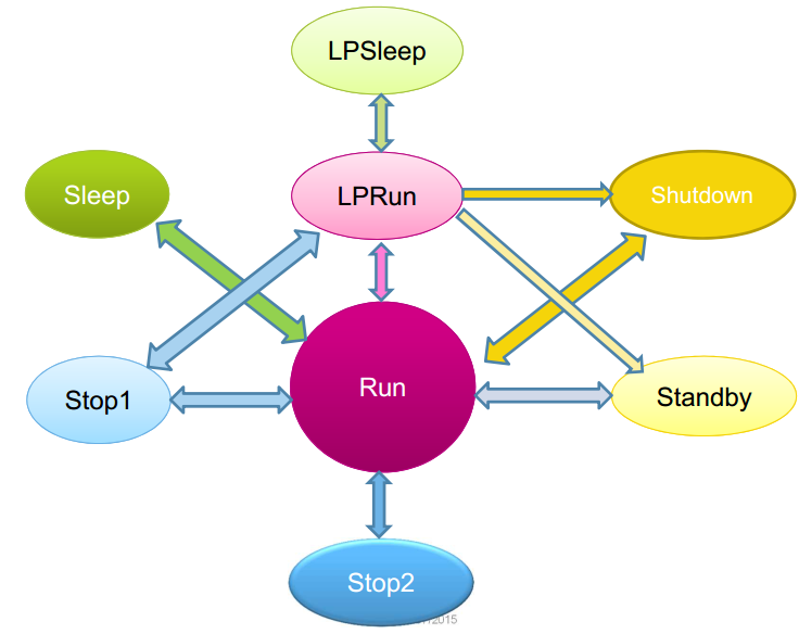
The STM32L4 series is an ultra-low power Crotex-M4 core MCU launched by ST company, which supports multiple power management modes. Among them, in the lowest power consumption Shutdown mode, the standby current is only 30 nA. ST company divides the L4 series electrical tube management into many types, but the characteristics of each mode are not characterized by a gradual decrease in power consumption. The following is a state transition diagram between each mode:
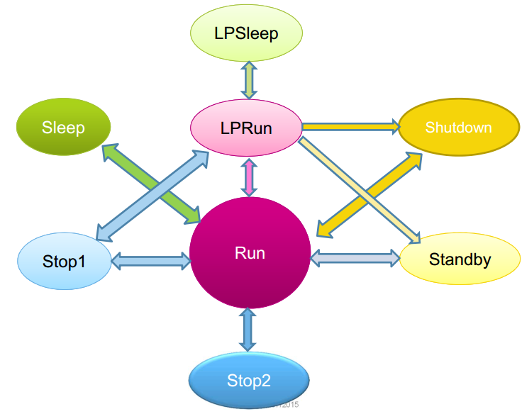
Although there are many low-power modes in the STM32L4 series, they are not inherently complex. Understanding their principles can help us transplant drivers and better select suitable modes in our products. The main factors that ultimately determine the power consumption of the STM32L4 series system are the voltage regulator, CPU operating frequency, and the low-power processing of the chip itself. The following will elaborate on each of the three factors.
Regulator L4 uses two embedded linear regulators to power all digital circuits, standby circuits, and backup clock domains, namely the main regulator (MR) and low-power regulator (LPR). The voltage regulator is in the enabled state after reset, and different voltage regulators are selected to supply power to the Vcore domain according to the application mode. Among them, the output voltage of MR can be configured by software to different ranges (Range 1 and Rnage 2). Application scenarios of voltage stabilizer
Vcore = 1.2V, Used for operating mode, sleep mode, and stop mode 0, MR does not provide full power in the Vcore domain
Used for low-power operation mode, low-power sleep mode, stop mode 1, stop mode 2
In Standby and Shutdown modes, both MR and LPR are turned off
The CPU operating frequency achieves the goal of reducing power consumption by lowering the CPU's main frequency: when MR operates in Range 1 normal mode, SYSCLK can operate at a maximum of 80M; When MR is working in Range 2, the maximum SYSCLK cannot exceed 26 M; Low power operation mode and low power sleep mode, where the Vcore domain is powered by LPR and SYSCLK must be less than 2M.
The low-power processing chip itself defines a series of sleep modes, such as Sleep, Stop, Standby, and Shutdown. The power consumption of the first four modes gradually decreases, which is essentially achieved by turning off peripherals and clocks inside the chip.
Configuration Engineering
Configure PM components:

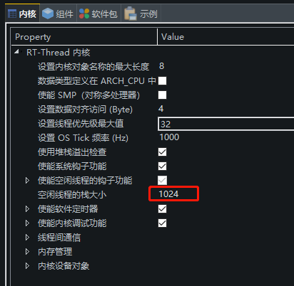
Configure kernel options: Using PM components requires a larger IDLE thread stack, which uses 1024 bytes
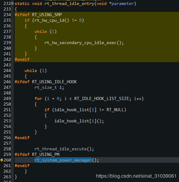
In idle threads, the rt_stystem_power_manager interface will be called to enter low-power mode:
/**
 * This function will enter corresponding power mode.
 */
void rt_system_power_manager(void)
{
    rt_uint8_t mode;

    if (_pm_init_flag == 0)
        return;

    /* CPU frequency scaling according to the runing mode settings */
    _pm_frequency_scaling(&_pm);

    /* Low Power Mode Processing */
    mode = _pm_select_sleep_mode(&_pm);
    _pm_change_sleep_mode(&_pm, mode);
}
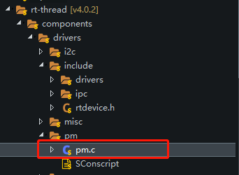
保存后,可以看到pm.c已经被添加到了工程:
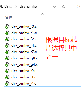
Then add the device driver for the PM component, with the latest address of the driver: pm-ports-stm32 new branch: https://gitee.com/sunwancn/rt-thread/tree/pm-ports-stm32-new Attention: The current driver used is not the latest version. Please download the latest PM driver from Gitee for porting.
Copy the following four files from \ rt thread \ bsp \ stm32 \ libraries \ HAL-Drivers to the drivers folder of the project:

The project chooses to use RTC as the time compensation after STOP, so it is necessary to open the RTC device and the macro used:

Note: If RTT's own RTC function is not used, the first two macros can be omitted.
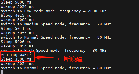
Application example: This program mainly implements entering STOP mode after 10 seconds of startup, and then switching between SLEEP mode and STOP mode every 5 seconds. This cycle repeats, and after one cycle, the MCU's operating frequency is switched to verify its stability. And it has enabled callback and interrupt wake-up, which will turn off and light up the LED lights respectively after entering sleep and wake-up. During sleep time, it can be awakened through external interrupts:
/*
 * Copyright (c) 2006-2018, RT-Thread Development Team
 *
 * SPDX-License-Identifier: Apache-2.0
 *
 * Change Logs:
 * Date           Author       Notes
 * 2018-11-06     SummerGift   first version
 */

#include
#include
#include
#include
#define LOG_TAG              "PM.test"
#define LOG_LVL              LOG_LVL_DBG
#include
/* defined the LED0 pin: PB13 */
#define LED0_PIN    GET_PIN(C, 6)
#define MCU_IRQ_WAKE_PIN   GET_PIN(C, 9)
static RTC_HandleTypeDef hrtc;
static RTC_TimeTypeDef curtime = {0};
static RTC_TimeTypeDef alarmtime = {0};
static RTC_AlarmTypeDef alarm = {0};
static struct rt_semaphore  wake_sem;
static rt_uint8_t sleep_mode = PM_SLEEP_MODE_DEEP; /* STOP 模式 */

static rt_uint8_t run_mode = PM_RUN_MODE_NORMAL_SPEED;

static rt_uint32_t get_interval(void);
static void get_rtc_time(RTC_TimeTypeDef *time);
static rt_uint8_t mode_loop(void);
static rt_uint8_t issleep = 0;
/* 中断回调函数 */
static void MCU_IRQ_WAKE(void *args)
{

    if(issleep)
    {
        rt_kprintf("MCU_IRQ_WAKE!\n");
        rt_sem_release(&wake_sem);
        issleep = 0;
    }

}
static void pm_botify(uint8_t event, uint8_t mode, void *data)
{

    if(event == RT_PM_ENTER_SLEEP && mode == PM_SLEEP_MODE_DEEP)
    {
        rt_pin_write(LED0_PIN, PIN_HIGH);
        issleep = 1;
    }
    else if (event == RT_PM_EXIT_SLEEP && mode == PM_SLEEP_MODE_DEEP )
    {
        rt_pin_write(LED0_PIN, PIN_LOW);
    }
}

int pm_test(void)
{
    hrtc.Instance = RTC;

    rt_sem_init(&wake_sem, "wake_sem", 0, RT_IPC_FLAG_FIFO);
    rt_pm_notify_set(pm_botify,0);
    /* 按键0引脚为输入模式 */
    rt_pin_mode(MCU_IRQ_WAKE_PIN, PIN_MODE_INPUT_PULLDOWN);
    /* 绑定中断,上升沿模式,回调函数名为beep_on */
    rt_pin_attach_irq(MCU_IRQ_WAKE_PIN, PIN_IRQ_MODE_RISING, MCU_IRQ_WAKE, RT_NULL);
    /* 使能中断 */
    rt_pin_irq_enable(MCU_IRQ_WAKE_PIN, PIN_IRQ_ENABLE);

    rt_thread_mdelay(10000);


#ifdef RT_USING_PM
    /* 申请低功耗模式 */
    rt_pm_request(sleep_mode);
#endif

    get_rtc_time(&curtime);

    if (sleep_mode == PM_SLEEP_MODE_STANDBY)
    {
        /* 设置休眠,闹钟 20 秒后唤醒,简化版闹钟,只支持 1分钟内有效 */
        alarmtime.Hours = curtime.Hours;
        alarmtime.Minutes = curtime.Minutes;
        alarmtime.SubSeconds = curtime.SubSeconds;
        alarmtime.Seconds = curtime.Seconds + 20;
        if (alarmtime.Seconds >= 60)
        {
            alarmtime.Seconds -= 60;
            alarmtime.Minutes ++;
            if (alarmtime.Minutes >= 60)
                alarmtime.Minutes -= 60;
        }

        alarm.Alarm = RTC_ALARM_A;
        alarm.AlarmTime = alarmtime;
        alarm.AlarmTime.DayLightSaving = RTC_DAYLIGHTSAVING_NONE;
        alarm.AlarmTime.StoreOperation = RTC_STOREOPERATION_RESET;
        alarm.AlarmMask = RTC_ALARMMASK_DATEWEEKDAY | RTC_ALARMMASK_HOURS;
        alarm.AlarmSubSecondMask = RTC_ALARMSUBSECONDMASK_NONE;
        alarm.AlarmDateWeekDaySel = RTC_ALARMDATEWEEKDAYSEL_DATE;
        alarm.AlarmDateWeekDay = 0x1;

        /* 开启闹钟 */
        HAL_RTC_SetAlarm_IT(&hrtc, &alarm, RTC_FORMAT_BIN);
    }

    while (1)
    {
        /* 开始进入低功耗模式 */
        rt_sem_take(&wake_sem, rt_tick_from_millisecond(5000));

        /* 退出低功耗模式 */
        rt_kprintf("Sleep %d ms\n", get_interval());

#ifdef RT_USING_PM
        /* 申请正常模式 */
        rt_pm_request(PM_SLEEP_MODE_NONE);
#endif

        rt_thread_mdelay(5000);

        rt_kprintf("Wakeup %d ms\n", get_interval());

        /* 运行模式切换 */
        rt_pm_run_enter(mode_loop());

#ifdef RT_USING_PM
        rt_pm_release(PM_SLEEP_MODE_NONE);
#endif
    }

    return RT_EOK;
}
//MSH_CMD_EXPORT(pm_test, PM TEST);

static rt_uint32_t get_interval(void)
{
    rt_uint32_t seconds;

    rt_uint32_t last_seconds = curtime.Seconds;
    rt_uint32_t last_subseconds = curtime.SubSeconds;

    get_rtc_time(&curtime);

    if (curtime.Seconds < last_seconds)
        seconds = 60 + curtime.Seconds - last_seconds;
    else
        seconds = curtime.Seconds - last_seconds;

    return (rt_uint32_t)(seconds * 1000 + ((int32_t)last_subseconds - (int32_t)curtime.SubSeconds) * 1000 \
                         / (int32_t)(((RTC->PRER & RTC_PRER_PREDIV_S) >> RTC_PRER_PREDIV_S_Pos) + 1U));
}

static void get_rtc_time(RTC_TimeTypeDef *time)
{
    rt_uint32_t st, datetmpreg;

    HAL_RTC_GetTime(&hrtc, time, RTC_FORMAT_BIN);
    datetmpreg = RTC->DR;
    if (HAL_RCC_GetPCLK1Freq() < 32000U * 7U)
    {
        st = time->SubSeconds;
        HAL_RTC_GetTime(&hrtc, time, RTC_FORMAT_BIN);
        datetmpreg = RTC->DR;

        if (st != time->SubSeconds)
        {
            HAL_RTC_GetTime(&hrtc, time, RTC_FORMAT_BIN);
            datetmpreg = RTC->DR;
        }
    }
    (void)datetmpreg;
}

rt_uint8_t mode_loop(void)
{
    rt_uint8_t mode = 1;

    run_mode++;
    switch (run_mode)
    {
    case 0:
    case 1:
    case 2:
    case 3:
        mode = run_mode;
        break;
    case 4:
        mode = 2;
        break;
    case 5:
        mode = 1;
        break;
    case 6:
        mode = run_mode = 0;
        break;
    }

    return mode;
}
运行效果:
